Eight ports serial to Ethernet converters are used to realize the bidirectional transparent transmission of data from the serial port to the Ethernet port, and usually converse the data between RS232 / RS485 / RS422 interfaces. USRIOT recently launched an eight-port serial device server USR-N668. All serial port package is RJ45 port form, and can be converted by RJ45 adapter board and DB9 pin serial port. However, if the pin definition of the eight ports serial device server is unclear, it will inevitably affect the connection situation in the project site.
The serial command of eight ports serial device server
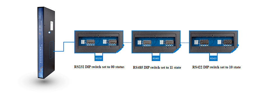
There is a DIP switch setting window on the back of the device .
It can be seen after the screws is removed by a cross-blade screwdriver. Once it is set up,you don't need to worry about error touching forever.
The following is the setting instructions for the DIP switch.

A total of 16 (8 serial ports * 2) dialing code. The device has 8 serial ports, each with 2 dialing codes, as shown in the figure.
Note
According to the illustration, based on the wire stamp, dialing to the top represents 1 and dialing to the bottem represents 0.
The order of the two dial codes is represeted from left to right
The factory is in RS232 mode, that is, they are all dialed at 0 0
Serial pin definition
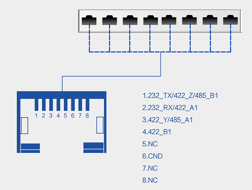
The following figure shows the description of the serial port pin (hardware interface type is RJ45).

|
No. |
Name |
Function |
|
1 |
232_TX / 422_Z / 485_B1 |
232 sending;422 signal Z;485 signal B |
|
2 |
232_RX / 422_A1 |
232reception,422 signal A |
|
3 |
422_Y / 485_A1 |
422 signal Y;485 signal A |
|
4 |
422_B1 |
422 signal B |
|
5 |
NC |
|
|
6 |
GND |
232signal earth |
|
7 |
NC |
|
|
8 |
NC |
|
note
One is chosen from 232, 485 and 422 , and only one way can be used towork at the same time
The correct DIP switch is needed to match
Since the hardware interface is RJ45, you need to use 8-core cable cable + crystal head to make communication cable.
The indicator description of eight ports serial device server
The numerous indicator lights of USR-N668 make it easier for customers to observe the working status of the 668.

The state and function of the various lamps are mainly described below.
Power PWR red / it is always on after power-on
Work indicator WORK green / The cycle flashes after the start is completed. It is bright 500ms, and it is off for 500ms.
Status indication STATE red / function undefined (reserved)
It is ready READY green / The device works normally, and it is always on; it does not work, and it i s off for a long time.
Serial port transmission * 8TXN red / serial port N transmission indication, it flashes when there is data
Serial port reception * 8RXN green / Serial N receiving indication, it flashes when there is data


